There are plenty of Mac mini case modification projects on the internet. Though the unibody aluminum housing design had been there for almost a decade, it’s still the best looking mini computer case on the market imo.
In mid 2019, Raspberry Pi receive a huge update - the Pi 4. We finally got true gigabit ethernet, USB3.0 support, and a lot more. This makes Pi 4 suitable for simple NAS project (also for TimeMachine backup). So I decide to build a fake(?) TimeCapsule with Pi (at least the case is real, or should I just call it “Fake Mac mini” ? lol)
This article will show how I build this project, and the issue that I ran into (hardware side, the software configuration can be found at: Use Raspberry Pi to build a FAKE TimeCapsule - Software, Use Raspberry Pi as a NAS)(haven’t translate to English yet).
Idea && Design
(https://static.driftking.tw/2024/06/e39d19076b26e35c8b8e075f87a977ed.jpg)
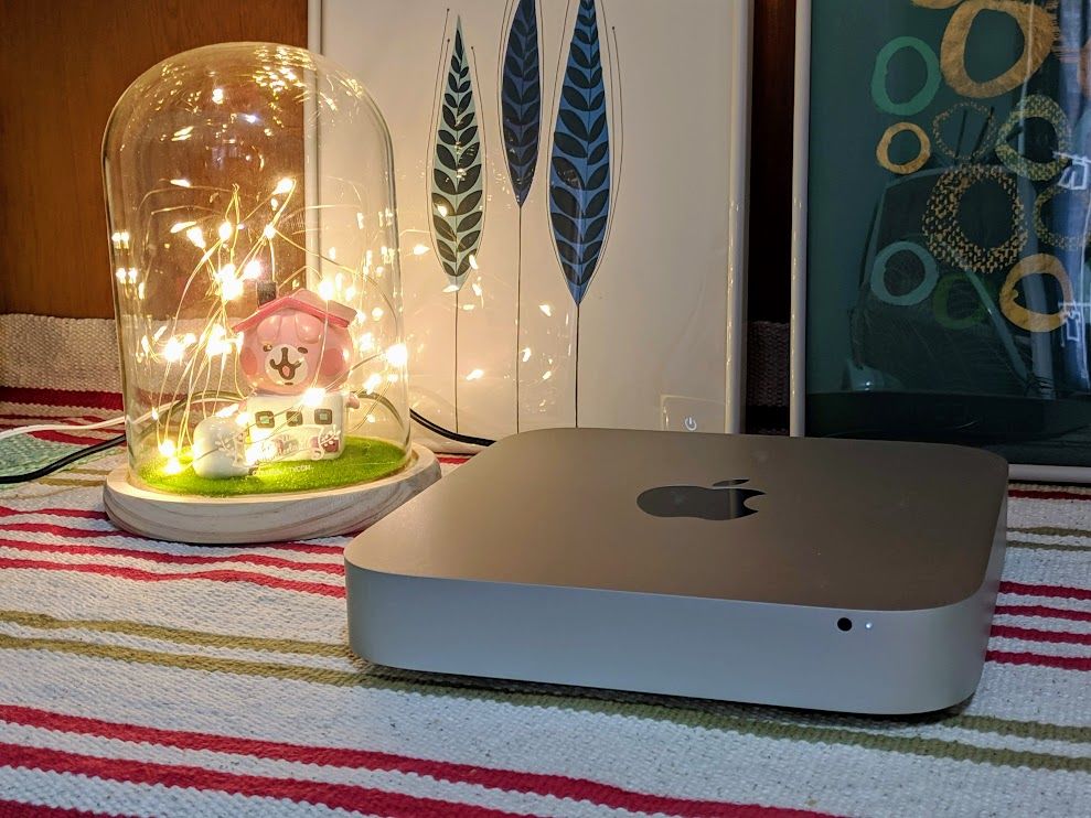
I bought this used Mac mini case for cheap (around 20USD), it still in very good shape. You can buy it from ebay or AliExpress.
First, let’s do some simple measure. The maximum motherboard you can put inside is around 17cm*17inch (lots of people use Mini-ITX in Mac mini’s case.) Height is about 2.5cm, for our Pi project is more than enough.
Here’s the first design diagram (the hub will cause some issue so I connect the HDDs direct to Pi in final product, see Troubleshooting):
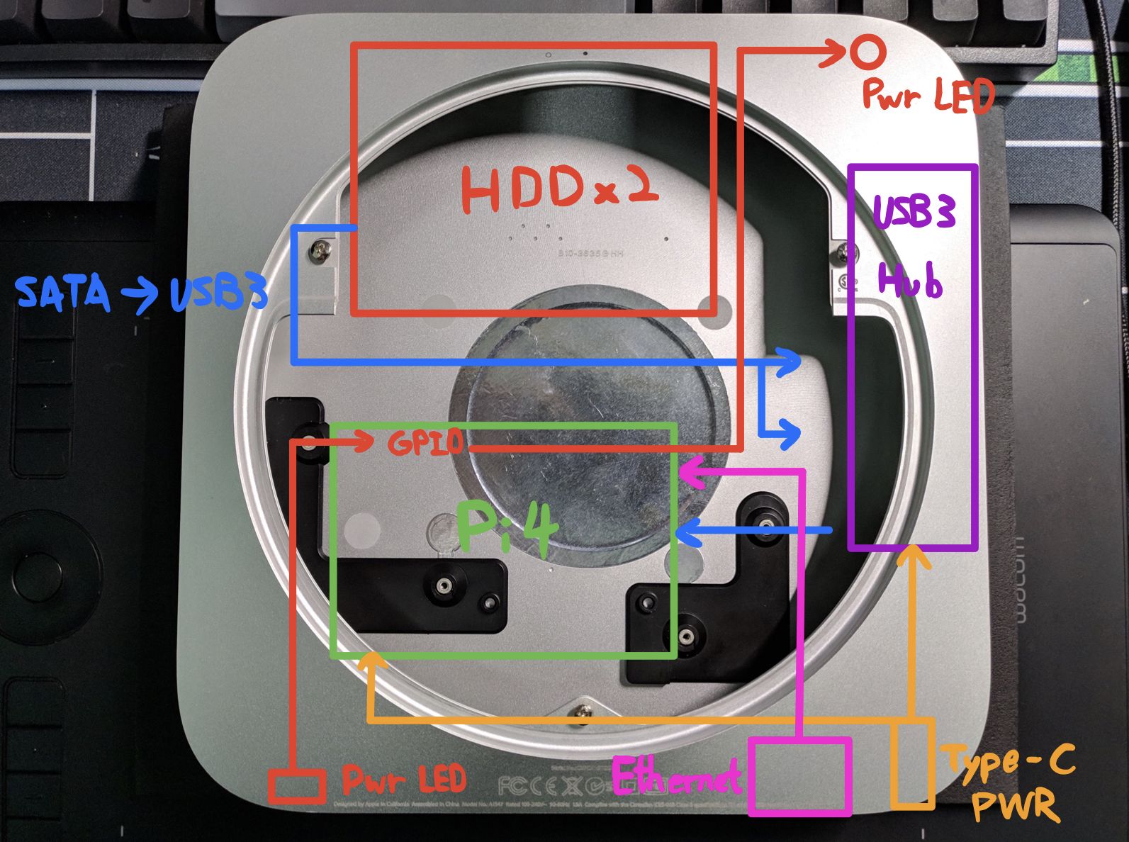
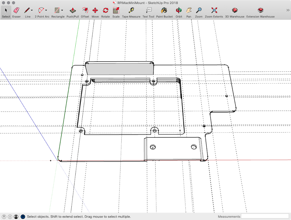
All I need to do is mount these things up. So I decide to draw some 3D printed files to do the job.
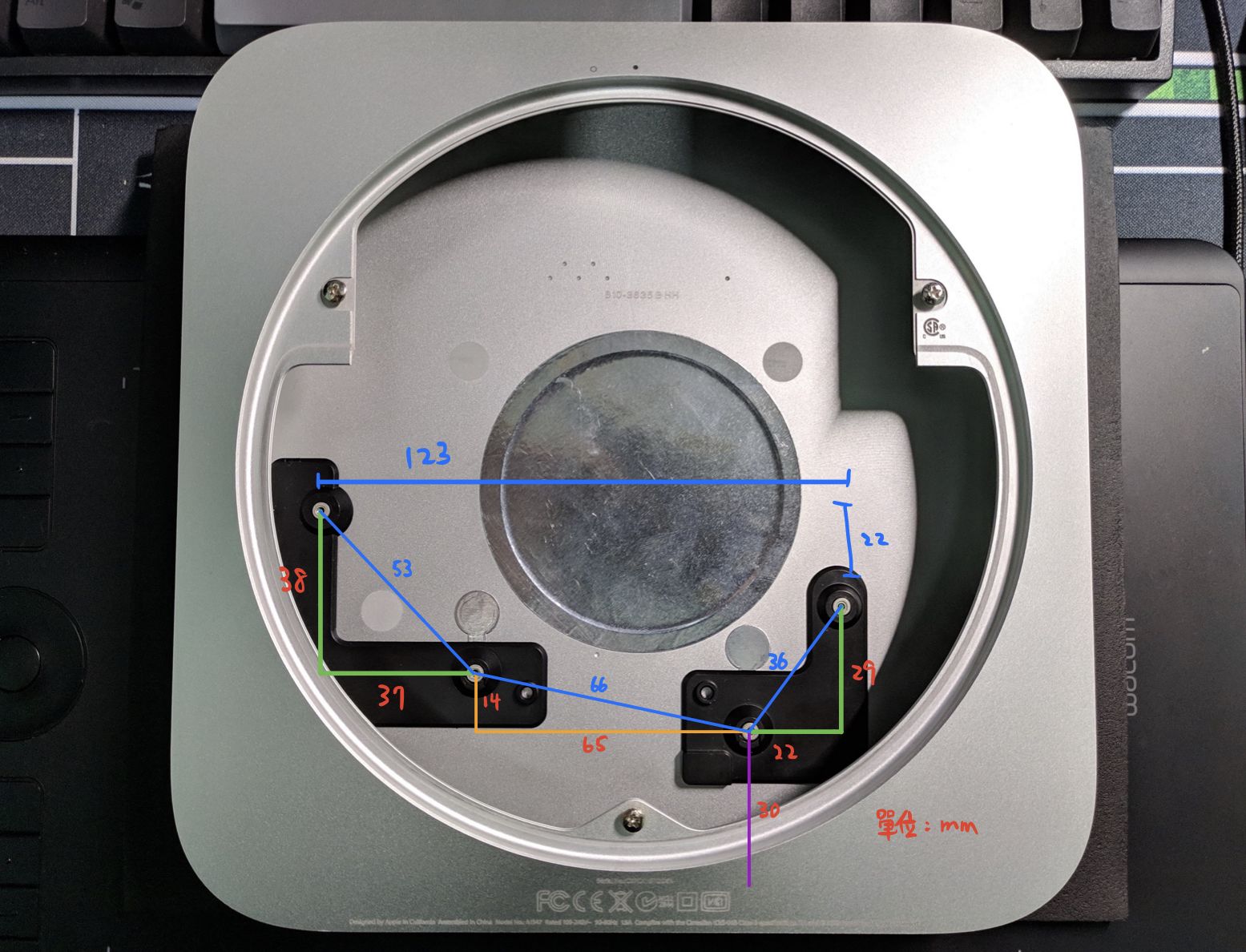
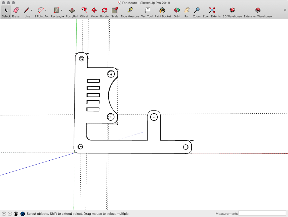
And here’s the diagram that shows each mounting hole’s distance I measured.
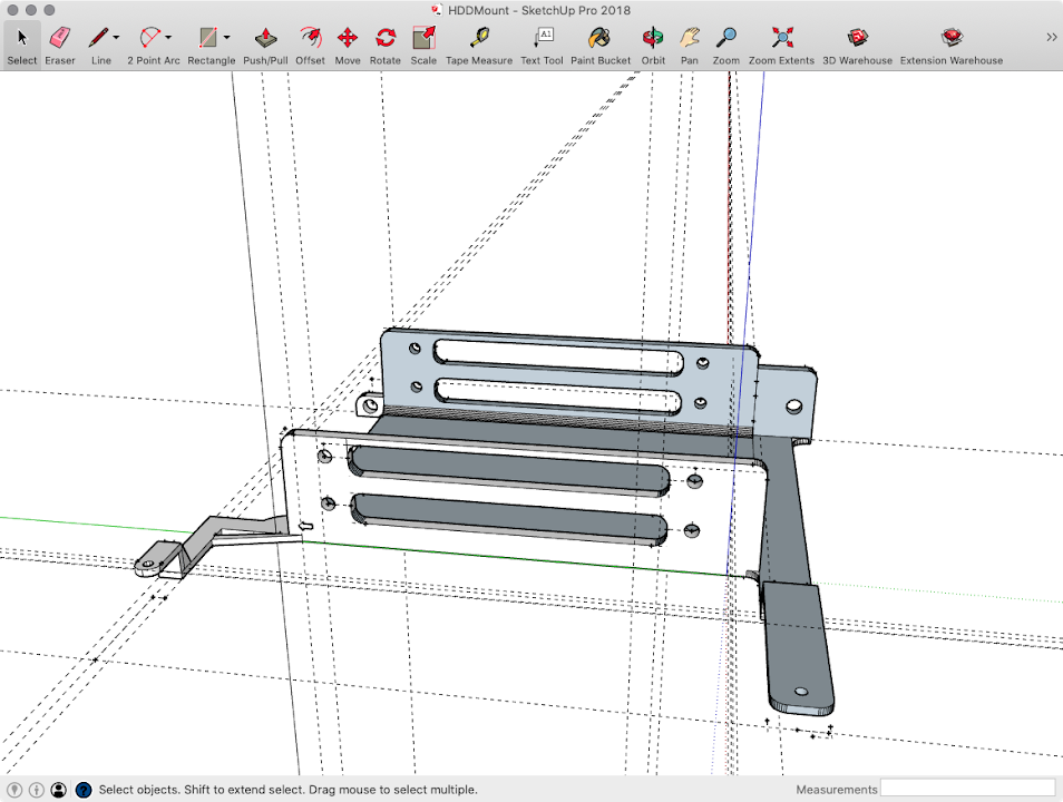
Next, the HDD mount. The arm on both side aren’t strong enough, so I just cut them off.
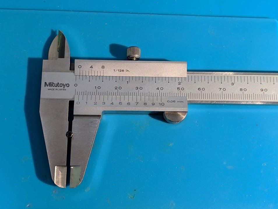
Here comes the tricky part. Unfortunately, there’s no information about the mounting screw for Mac mini case. ifixit only says it’s four 7.9mm long Torx screw, didn’t mention the shaft diameter.
I tried several screw that I have, luckily, one screw can screw in and quite stable. So I can use caliper to measure it’s size: 1.7mm (You can use M1.7 phillips tapping screw instead of official torx screw)
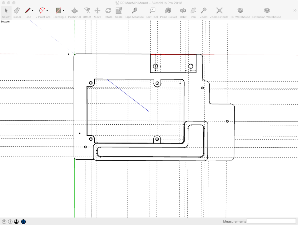
Pi mounting plate. An isolation brick to protect GPIO pins is nice to have:
Make some feet under the mounting plate.
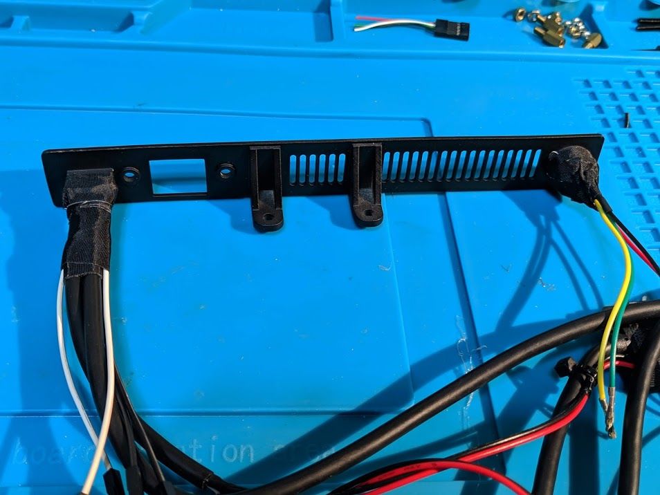
The I/O shield (the plastic frame for Mini-ITX I/O shield is brought from other maker) Left side is for USB-C female connector and ethernet extender cable, right side for momentary power switch.
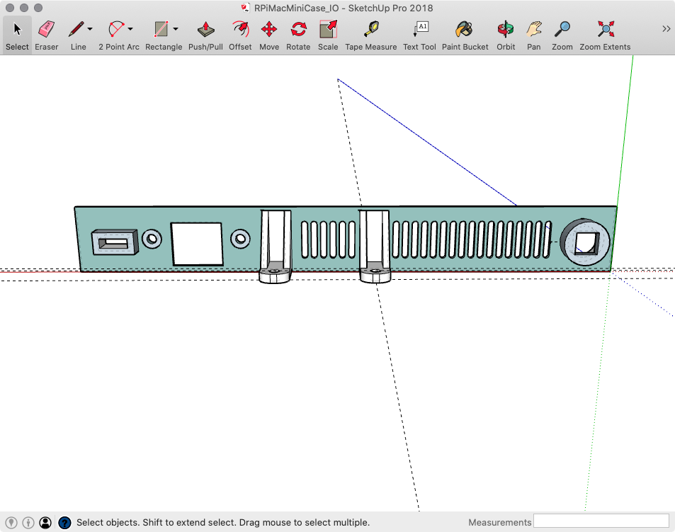
I made some mistake about the side mounting holes on I/O shield, so just ignore it. (The ethernet extender cable’ screw can hold I/O shield in place) Also need to cut the Pi mounting plate to fit in the case.
Finally, the 30mm fan mount:
The STL files I used in this project can be download at: PiMacMiniCaseSTLFiles
Installation
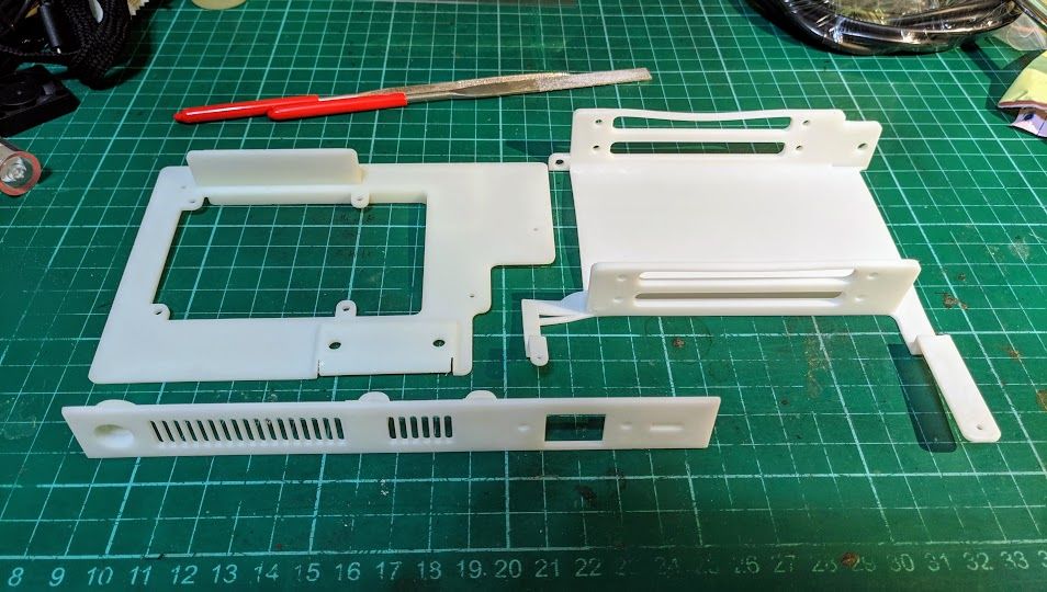
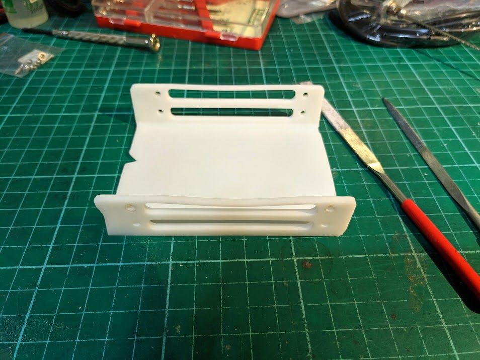
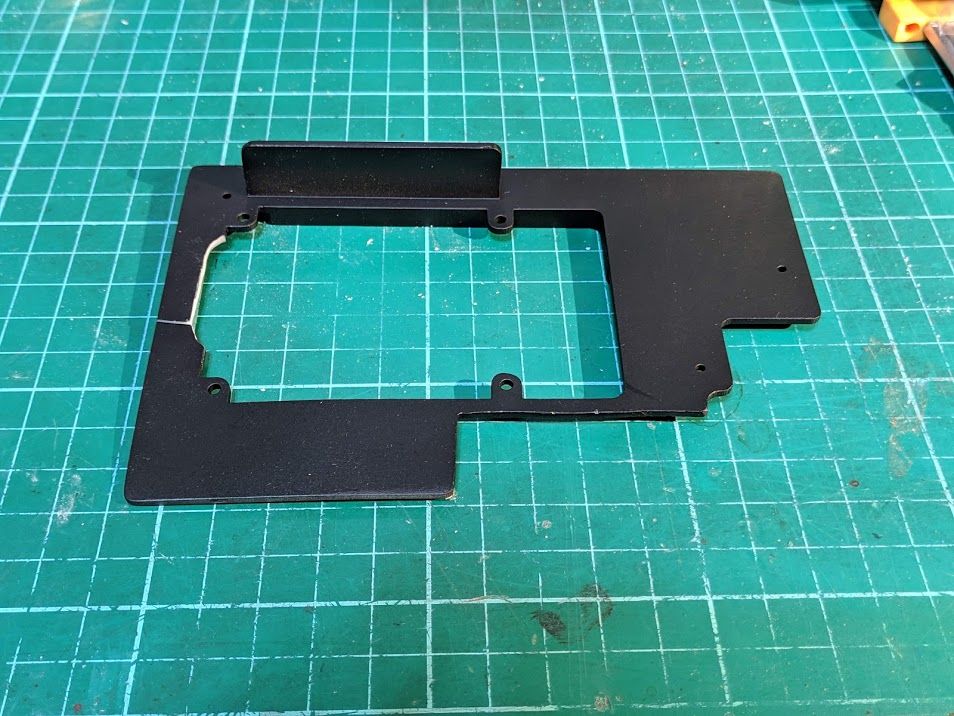
Alright, here’s the finished 3D printed items. (SLA Resin)
I’ve found that the holes on I/O shield are a bit too small. So need to enlarge the Type-C and switch hole for a better fit.
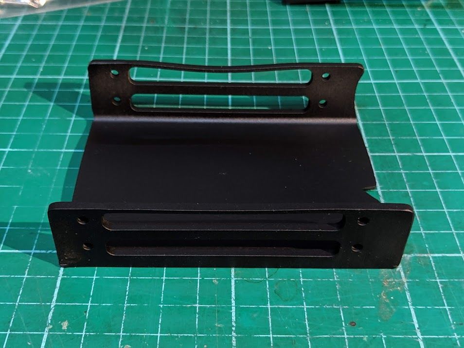
Sand down the surface and paint them in matte black.
Ouch! There’s a crack on the edge when I try to trim it. But since it’s hide in the case, not a big deal.
And I forgot the Micro SD on pi protrudes from the edge, so more trimming work need to be done.
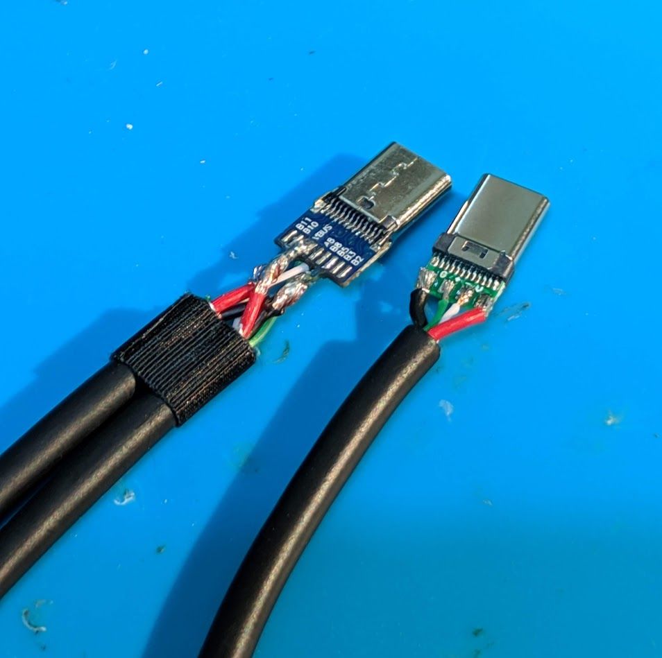
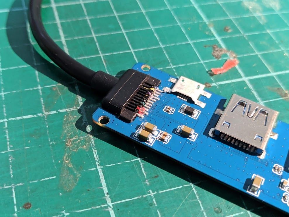
Then opens up the USB to SATA cable and cut out the VCC connect on board.
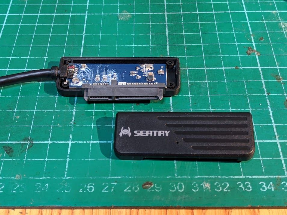
Use some electrical tape to cover the board.

Remember to check the pins with multimeter, make sure we didn’t ruined the cable.
Screw in HDDs and test the mount.
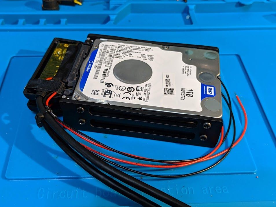
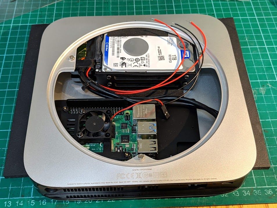
And solder the power line to Type-C connector. One for HDDs, other for Pi.
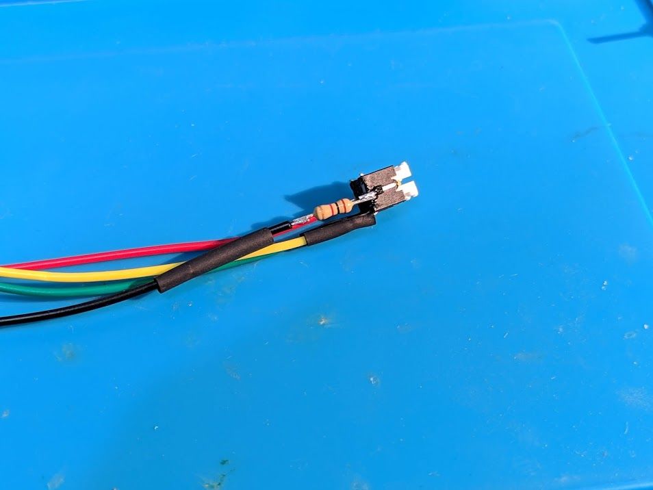
Momentary switch with LED. I use 1k Ohm resistor here.
About the wiring diagram you can check my other article: Raspberry Pi - Power switch, External power LED, SD Act LED(Haven’t translate to English yet)
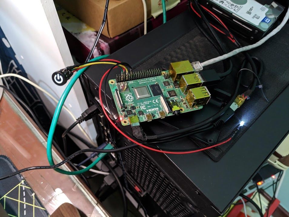
Test it!
Glue the power switch and Type-C connector in place.
Some simple wiring.
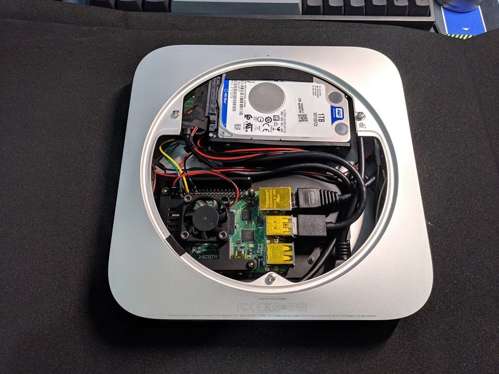
Put on the bottom cover.
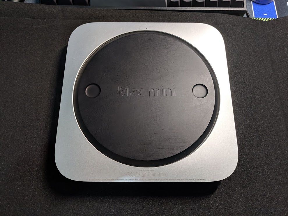
Done!
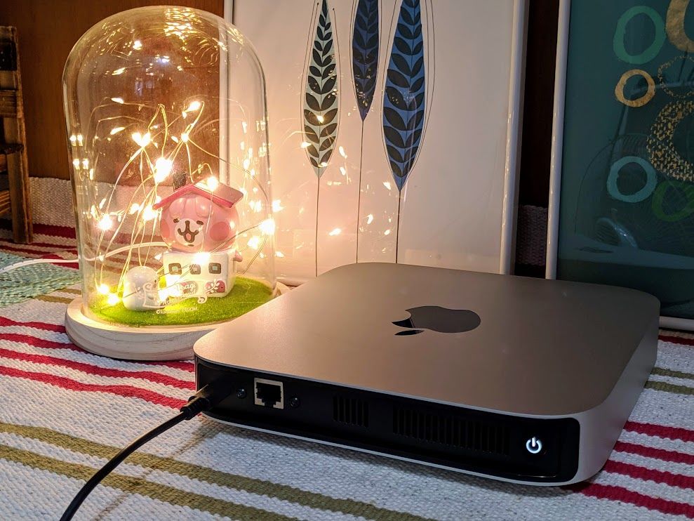
Bay ~
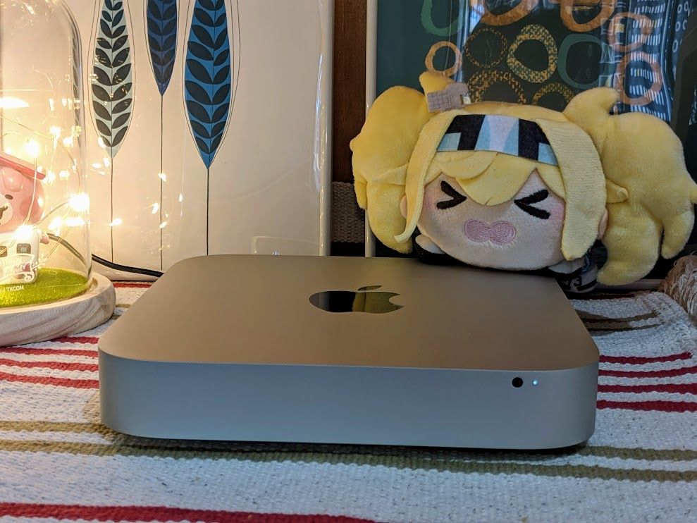
OK I think it just looks like a real Mac mini
PS The max cpu temperature is around 50°C (room temp:26~28°C)
Troubleshooting
Mac mini housing screw spec?
I use phillips M1.7 x 6mm tapping screw.
USB powered hub issue
Some usb 3 powered hub will prevent Pi 4 from booting, here’s some discussion on Pi’s official forum: Pi 4 fails to boot when active USB switch attached. You can unplug the powered hub and plug it back. Pi will starts to boot and everything worked fine, but it’s really annoying.
Some people reports that cut out the Vcc on hub can solve the issue, but I tried and nothing happened :(
So I end up modify the USB to SATA cable instead.
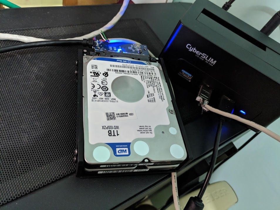
HDD and pi both using a 3A Official Power Supply?
I actually connect 2 HDD and Pi to the same power source, which is an official power supply. The main reason I do this is to avoid Pi’s USB port maximum 1.2A downstream limit.
I’ve measure the current drain on both HDD(w/ USB to SATA cable) and Pi, and it’s enough to be powered by a 3A power supply (my WD HDD’s peak current when activating is about 750mA) but can’t be power direct through Pi’s USB port due to 1.2A current limit. (I tried to connect direct to Pi’s USB, and one HDD fail to mount)
Note that 1 HDD is fine to direct plug it into Pi’s USB port.
Item list
- 1 x Pi 4 4GB
- 1 x 8G MicroSD Card for boot
- 1 x A1347 Apple Mac mini Case (Mid 2010)
- 2 x 2.5” HDD
- 2 x SATA to USB3 Cable
- 3D Printed Mount / IO Panel
- 1 x 30mm Fan
- 1 x Momentary Switch w/ LED & Cap
- 1 x 3mm Front Panel LED
- 2 x Current-limiting Resistor (330Ω ~ 1kΩ)
- 1 x Gigabit Ethernet Network Extension Cable
- 1 x USB Type-C Male Connector w/ PCB
- 1 x USB Type-C Female Connector w/ PCB
- Some USB Cable (Current support 3A at least)
- 3 x M3 Screw && M3 Hex Nut for Fan Mounting
- 4 x M3 Screw for HDD Mounting
- 2 x M3 Screw for Ethernet Port Mounting
- 3 x M1.7 Tapping Screw for Case Mounting w/ M2 Washer
- Some DuPont Line

Comments